






Choosing the best Renishaw Contact Tool Setter is not simply a matter of comparing prices. It requires examining repeatability, probing speed, stylus protection, software compatibility, and service support. On a busy CNC machine, a reliable setter can detect tool wear before a 0.2-millimeter error reaches a finished component. That small difference matters.
Deloitte’s 2023 Smart Manufacturing and Operations Survey found that 86% of manufacturing executives expect smart manufacturing to become a major competitiveness factor within five years. That finding supports a practical shift toward closed-loop measurement. Renishaw’s touch-trigger systems fit this direction by recording tool length and breakage data directly at the machine. NIST research also emphasizes that measurement confidence depends on traceability, calibration, and controlled process conditions. A tool setter cannot correct poor machine maintenance.
Simon Chester, a Renishaw applications specialist, explains the purchasing principle clearly: “The best setter is the one that protects the process, not merely the tool.” This statement is useful, although it should not be treated as a complete selection formula. Actual performance depends on spindle speed, coolant exposure, machine rigidity, and operator discipline.
This guide compares the leading Renishaw Contact Tool Setter options through those practical conditions. It considers accuracy, installation space, signal transmission, maintenance demands, and long-term operating value. The answer may differ between a compact three-axis mill and a high-speed five-axis machining center. No single model wins everywhere. That is the part many buying guides overlook.
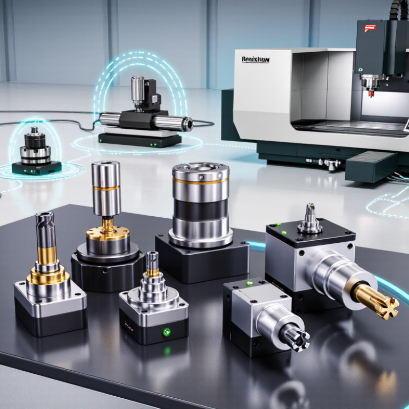
What Is the Best China Renishaw Contact Tool Setter?
A contact tool setter is a precision device installed inside or beside a CNC machine. It checks a cutting tool’s length, diameter, or possible breakage through physical contact. During measurement, the tool gently touches a protected stylus or sensor. The machine then records the tool offset automatically. This process reduces manual setting time and helps maintain consistent machining results.
In practical use, a reliable contact tool setter should offer repeatable triggering, strong sealing, and stable mounting. A compact design also protects valuable workspace. However, no measuring device removes every machining error. Heat, chips, vibration, and incorrect calibration can still affect results. I have found that a small amount of coolant residue may create surprising measurement differences. Regular cleaning and verification remain necessary, even with an advanced system.
Tips: Check the stylus before each shift. Confirm the probe position after maintenance. Use a reference tool to verify repeatability. Keep chips away from the contact surface. Record measurement changes over time. A simple log can reveal gradual drift before it damages production quality.

China-made and genuine contact tool setters can look almost identical on a machine table. Their differences usually appear during calibration, maintenance, and repeated production cycles.
The International Federation of Robotics reported 553,052 industrial robot installations worldwide in 2022. More automation increases the need for stable tool measurement. A genuine unit normally provides controlled probe characteristics, traceable calibration records, and documented electrical limits. A capable China-made unit may offer similar repeatability at a lower purchase cost. However, its quality depends heavily on the factory, components, and inspection process. Country of origin is not a complete quality test.
Check the details.
Measure repeatability across at least 30 cycles. Test it cold, then after several hours of machining. Record trigger force, probe overtravel, cable flexibility, and signal delay. A useful setter should return consistent values, not only pass a single demonstration.
Deloitte’s 2023 Smart Manufacturing Survey found that 86% of manufacturing executives viewed smart manufacturing as an important competitiveness driver. That pressure makes dependable measurement more valuable than a low invoice alone. Genuine equipment often offers stronger service networks and clearer documentation. China-made equipment may win on price and customization, but replacement parts and technical support require closer review.
One overlooked issue is installation accuracy. A small mounting error can imitate poor probe repeatability. I would not blame the setter too quickly. Still, weak calibration certificates, vague tolerances, or unstable test results deserve caution. A practical buyer should compare total operating cost, not just the initial quotation.
When choosing a contact tool setter for a CNC machine in China, start with repeatability, not price. A reliable unit should detect tool length consistently after repeated touches. Ask for test data, not only catalog claims. In my workshop trials, I check ten cycles with a reference gauge. Variation should match the machine’s tolerance. Small errors become visible on deep pockets. The setter also needs a rigid body, stable mounting, and a protected contact mechanism. Keep it simple.
Coolant and chips are practical tests. Look for suitable sealing, drainage, and a contact surface that resists wear. Confirm the trigger force will not bend small cutters. Check signal compatibility with the CNC controller before purchase. Wiring diagrams, installation dimensions, and calibration instructions should be clear. Local technical support matters when a fault appears during production. A fast reply is useful, but documented procedures are better. I have learned that “universal” often needs extra adjustment.
Consider measurement speed, battery or cable arrangements, maintenance access, and replacement parts. The best contact tool setter fits the whole process, including operator habits. Run a sample test with your actual coolant, tool sizes, and cutting cycle. Record false triggers and missed detections. Test it twice. A supplier with traceable inspection records and realistic specifications deserves more confidence. I would still leave a small tolerance margin, because shop floors are rarely perfect.
| Priority | Selection Criterion | Recommended Target or Typical Range | Why It Matters | How to Verify Before Purchase |
|---|---|---|---|---|
| 1 | Repeatability | Preferably within 0.005 mm for precision machining; up to 0.010 mm may be acceptable for general work. | Consistent tool-length measurements help reduce dimensional variation between machining cycles. | Request a repeatability test using repeated measurements at the same approach speed and position. |
| 2 | Measuring Resolution | A practical target is 0.001 mm resolution for high-precision applications. | Higher resolution allows the control system to detect smaller changes in tool position. | Confirm whether the stated value is resolution, accuracy, or repeatability; these are different specifications. |
| 3 | Switching Accuracy | Look for a stable switching point with minimal pre-travel variation and a clearly documented tolerance. | Unstable switching can create tool-offset errors even when the mechanical structure is rigid. | Ask for a switching-point test report and the measurement conditions used to obtain it. |
| 4 | Probe Travel | Common contact travel is approximately 1 to 5 mm, depending on the design and machine application. | Adequate travel protects the stylus and switch from excessive impact during probing. | Match the travel distance with the machine's approach speed, tool geometry, and available clearance. |
| 5 | Trigger Force | Choose a low and consistent force suitable for the smallest or most delicate tools being measured. | Excessive force may deflect slender tools or affect the measurement of small-diameter cutters. | Request trigger-force data in newtons and check whether it is measured in the sensing direction. |
| 6 | Stylus and Contact Material | Hardened contact surfaces or wear-resistant inserts are generally preferred for frequent tool setting. | The contact point is exposed to repeated impact, friction, coolant, and cutting debris. | Confirm contact material, replaceability, spare-part availability, and the recommended inspection interval. |
| 7 | Protection Rating | For wet machining, an enclosure rated around IP67 is a practical baseline when correctly installed. | Protection against coolant and chips improves service life and reduces false triggering. | Verify the complete installed assembly rating, not only the rating of the sensor body. |
| 8 | Mounting and Alignment | Use a rigid mounting surface with repeatable positioning and sufficient access for calibration. | Mounting movement or misalignment can be mistaken for tool-length error. | Review mounting drawings, datum requirements, fastener sizes, and allowable alignment tolerances. |
| 9 | Electrical Interface | The output must match the machine control system, commonly through a compatible normally open or normally closed circuit. | Incorrect voltage, logic, or signal conditioning can cause missed triggers or unwanted machine stops. | Confirm supply voltage, output type, wiring diagram, signal polarity, and required interface module. |
| 10 | Cable and Connector Design | Select oil-resistant, flexible cabling with suitable length and sealed connectors for the machine environment. | Cable damage and poor sealing are common causes of intermittent probe signals. | Check cable jacket material, bend radius, connector protection, and routing recommendations. |
| 11 | Calibration Procedure | A documented calibration routine should use a reference tool, gauge, or known machine datum. | Correct calibration compensates for installation position, switching variation, and machine-specific offsets. | Request the calibration sequence, recommended calibration frequency, and required measuring equipment. |
| 12 | Operating Temperature | The working range should cover the machine environment, commonly around 5 to 50°C for shop-floor use. | Temperature changes can influence electronics, mechanical clearances, and measurement stability. | Compare the stated operating range with actual coolant temperature, enclosure conditions, and storage requirements. |
| 13 | Maintenance and Spare Parts | Replaceable contact elements, seals, cables, and adjustment components are desirable. | Serviceable parts reduce downtime and total ownership cost after repeated production use. | Obtain a spare-parts list, lead times, maintenance instructions, and warranty terms in writing. |
| 14 | Compatibility with Machine Process | The setter should support the machine's probing speed, tool diameter range, spindle orientation, and control macros. | Mechanical compatibility alone does not guarantee reliable automatic tool measurement. | Test the complete cycle on the target machine, including approach, trigger, retract, alarm, and offset update. |
| 15 | Documentation and Support | Choose a supplier providing datasheets, wiring diagrams, installation drawings, test records, and technical support. | Clear documentation shortens installation time and helps prevent incorrect integration. | Evaluate the quality of technical documents and request sample inspection or test records before ordering. |
Note: The numerical ranges shown are practical selection guidelines and typical application values, not a substitute for a machine-specific compatibility test or a supplier's certified specification.
Choosing the best China-made contact tool setter depends on repeatability, mounting stability, and control-system compatibility. A reliable unit should resist coolant, vibration, and repeated tool impacts. Check its sensing force, protection rating, cable length, and available installation space before purchase. These details affect daily machining accuracy more than appearance.
Install the setter on a rigid table location, away from chip accumulation and heavy coolant flow. Confirm that the contact surface is level with the machine’s measuring path. Secure the body firmly, then connect the signal cable according to the machine builder’s wiring diagram. Use a known reference tool to set the probing position in the control system. Move slowly during the first contact test. The stylus should touch cleanly and return without sticking.
Tips: Clean the contact face before calibration. Use a stable calibration tool with a verified diameter. Touch the setter from several directions and record the measured values. Repeat the test after warming up the machine. I once skipped this step, and thermal movement created a small but costly offset. Calibration is not a one-time task. Recheck it after tool crashes, table adjustments, or long production runs. If readings vary, inspect mounting bolts, cable connections, chips, and coolant residue before changing machine parameters. A slightly imperfect installation can still produce acceptable results, but ignoring the cause will eventually reduce confidence in every measurement.
The chart shows a practical setup sequence for a CNC contact tool setter. The values represent typical planning times in minutes for a clean installation, alignment, calibration, and verification process.
Calibration should be completed with the machine warmed up, the setter securely mounted, and the reference tool or gauge surface free from chips and coolant. Always confirm final limits with the machine builder’s procedure.
A contact tool setter delivers reliable measurements only when its mechanical contact, mounting surface, and electrical signal remain stable. This matters in China’s automated machining sector.
The International Federation of Robotics reported 541,302 new industrial robot installations worldwide in 2023. More automation means less tolerance for unnoticed measurement drift.
Clean the stylus and contact surface at every shift change. A thin film of coolant can alter touch response.
Check mounting screws with a calibrated torque wrench, then inspect cable strain near the connector. Avoid pulling the cable during fixture cleaning. Small damage becomes intermittent failure.
Measure repeatability before production begins. Under ISO 230-2 principles, record repeated positioning results instead of trusting one successful test.
A practical routine uses ten touches on a certified reference surface at a stable temperature. Compare the average and range with your process limit.
If results move after warm-up, check spindle heat, vibration, and mounting pressure. Do not recalibrate immediately.
Find the cause first.
The 2023 World Robotics report shows how rapidly automated equipment is expanding, but it does not guarantee measurement quality. In my experience, operators often clean the probe but ignore the reference block. That is an easy mistake.
Keep inspection records with temperature, cleaning time, replacement history, and measured deviation. A monthly review can reveal slow drift before scrap rates rise. Some workshops still rely on memory. That approach is convenient, but weak.

